The site decision and observation unit
This guide examines multispectral band alignment when a mapping team needs to coordinate mapping of built features beside a changing shoreline. The goal is to connect a specific technical choice to observable site evidence, an independently checkable comparison and a clear delivery decision.
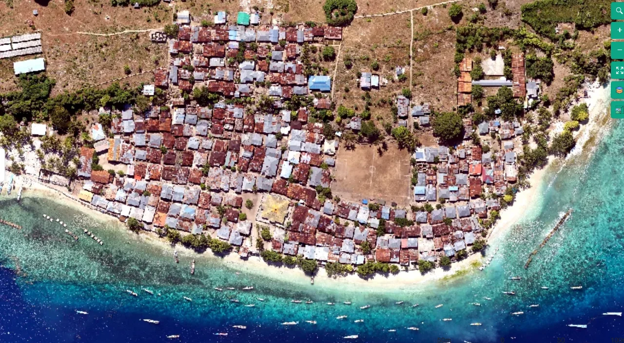
Define buildings, access routes, visible shoreline indicators and water as separate layers. Coastal settlements combine roof occlusion with tide-dependent visibility. Record the shoreline indicator used and the acquisition time. A current orthomosaic can assist inspection and planning, while legal property boundaries require their own authoritative evidence.
Define the decision before choosing a processing configuration. State the target object, the observable surface, the required geographic reference and the evidence needed by the receiving user. Separate direct observations from inferred values. This prevents an attractive image from becoming an unsupported claim about conditions that the sensor did not observe. Preserve the project question in the run record so later quality review evaluates the intended use rather than a convenient software statistic.
The technical mechanism
Multispectral sensors may observe bands through different optical paths or at slightly different times. Misalignment creates false spectral contrasts at edges and small objects. A composite can look convincing at overview scale while individual pixels combine different ground supports. Quantitative indices therefore depend on suitable band geometry as well as radiometric preparation.
Site conditions that can mislead interpretation
Roof overhangs differ from ground footprints, narrow lanes may be hidden and water glint removes shoreline detail. Different tide or wave conditions can dominate apparent coastal change. A roof displacement in an orthomosaic may reflect geometry rather than a moved structure. Avoid treating every visible edge as a surveyed boundary.
Matching raster dimensions does not prove band alignment. A one-pixel disagreement may matter greatly when the target occupies only a small number of cells.
Prepare the inputs and the controlled test
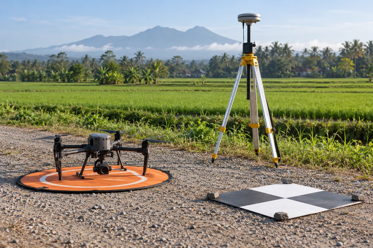
Preserve sensor calibration and capture metadata. Inspect recognizable edges in each band and review the alignment method. Test representative terrain, canopy and high-contrast boundaries. Keep the source bands and validity masks available instead of treating a rendered false-color preview as the analytical data.
Build the comparison around a preserved baseline. Use the same input inventory, geographic extent and independent reference observations whenever the experiment permits. Change one justified factor at a time and record any unavoidable difference. Select both a difficult inspection region and a stable control region before examining the candidate output. Compare on their common valid support, then report any gain or loss of total coverage separately. This distinguishes a local improvement from a result that merely excludes the hardest observations.
Independent verification in this setting
Check selected access connections, building identifiers and shoreline indicators on the ground where appropriate. Record the observation time and reference information used for comparison. Inspect occluded lanes separately from clear roads. Keep positional checks independent from any features already used to constrain or align the reconstruction.
Compare edge correspondence and index behavior in narrow or mixed features. Check independent reference observations relevant to the intended classification. Review whether alignment improves one area while degrading another. Document the output grid and resampling because these choices affect the support of the combined spectral values.
A linked check: Training and Validation Separation
A classification must be evaluated on observations independent from those used to develop it. Nearby pixels or fragments of the same object can share texture and context, so a random pixel split may exaggerate generalization. The intended use determines whether validation should separate objects, blocks, dates or sites.
Define the target classes and the unit of independent evaluation before selecting samples. Preserve identifiers linking labels to their source evidence. Separate development and evaluation locations at a meaningful spatial or operational level. Include difficult boundaries, rare classes and ordinary negatives rather than constructing an artificially easy test set.
Report class-specific errors and the population represented by the sample. Inspect both false alarms and missed targets. Keep the validation labels fixed while comparing candidates. If the model is revised after examining the test, retain another suitable independent assessment for the resulting claim.
An illustrative decision example
Imagine an illustrative classification that identifies unusual patches successfully in the clear interior of a site but performs poorly in shadow and mixed boundaries. A test restricted to the easiest interior examples will overstate its usefulness for operational inspection. Evaluate the relevant observation conditions separately and include ordinary unflagged areas so missed targets can be investigated. Where a spectral or thermal contrast is involved, preserve the calibration and environmental context before assigning a cause. A field visit may show that similar image patterns have different explanations. Keep the observation, candidate interpretation and verified finding as separate records. This example supplies no accuracy percentage or measured site result. It shows why a useful remote-sensing product needs an independently defined target, representative evaluation and a clear uncertainty class rather than a complete-looking map that assigns every pixel an unjustified confident label.
Interpret uncertainty before accepting the result
Write the acceptance rule before selecting the most attractive output. The actual threshold must follow the project purpose and the quality of the independent evidence. Inspect signed differences and spatial patterns as well as summaries. Investigate consequential outliers using their source observations instead of deleting them to improve a score. A result can be suitable for inspection planning while remaining unsuitable for a more demanding engineering or quantitative claim. State that intended-use boundary explicitly.
Deliver evidence that the next team can use
Deliver defined built-feature layers, observable shoreline segments and an uncertainty register. Distinguish interpretation from survey evidence. Planning teams should be able to trace each feature to its source date and understand why some ground-level connections remain unresolved.
Keep the accepted source dates, processing version, coordinate conventions, masks and reference evidence beside the delivered data. Reopen a representative output from a clean copy and confirm that the intended receiving application interprets it consistently. Identify any remaining unsupported areas and the additional observation that would resolve them. The next analyst should be able to reconstruct the decision without depending on a temporary browser session, an operator recollection or a file whose name merely says final.
Where a cloud workflow can help
Online Photogrammetry Software can simplify the transfer from an organized image collection to a shared review workflow, but it does not remove acquisition or validation responsibilities. Drone Collab can be considered as part of that workflow after the team checks the current published capabilities and the outputs required by the project. Start with a representative collection and evaluate the evidence, usability and handover together. Choose the workflow because it supports a defensible decision rather than because one preview looks particularly polished.