The site decision and observation unit
This guide examines surface change detection when a mapping team needs to build an interpretable city-feature inventory with stable identifiers. The goal is to connect a specific technical choice to observable site evidence, an independently checkable comparison and a clear delivery decision.
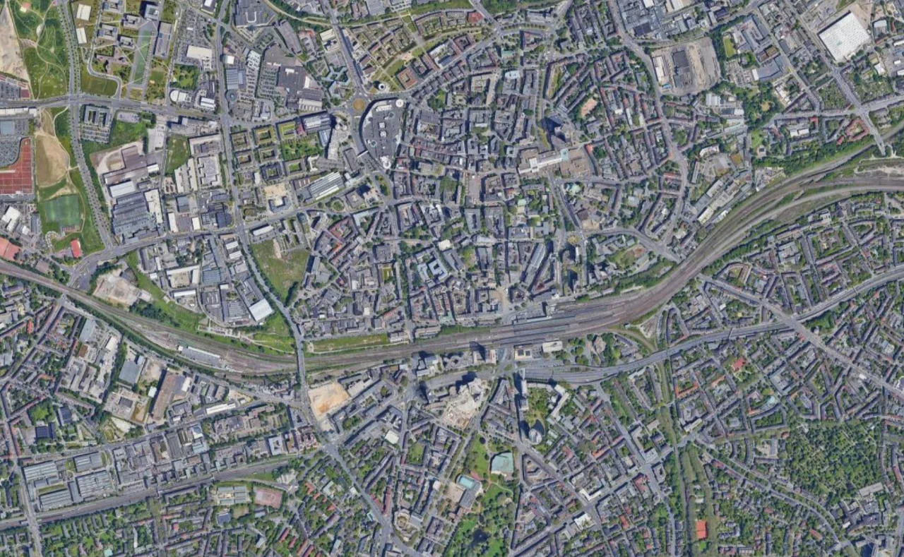
Define the object class before tracing: roof outlines, building footprints, road surfaces and parcel boundaries serve different purposes. Use stable identifiers and a documented interpretation scale. Dense urban blocks contain overlapping vertical surfaces, so a clean polygon is not necessarily the intended ground-level object. Record source date and observation limitations for each class.
Define the decision before choosing a processing configuration. State the target object, the observable surface, the required geographic reference and the evidence needed by the receiving user. Separate direct observations from inferred values. This prevents an attractive image from becoming an unsupported claim about conditions that the sensor did not observe. Preserve the project question in the run record so later quality review evaluates the intended use rather than a convenient software statistic.
The technical mechanism
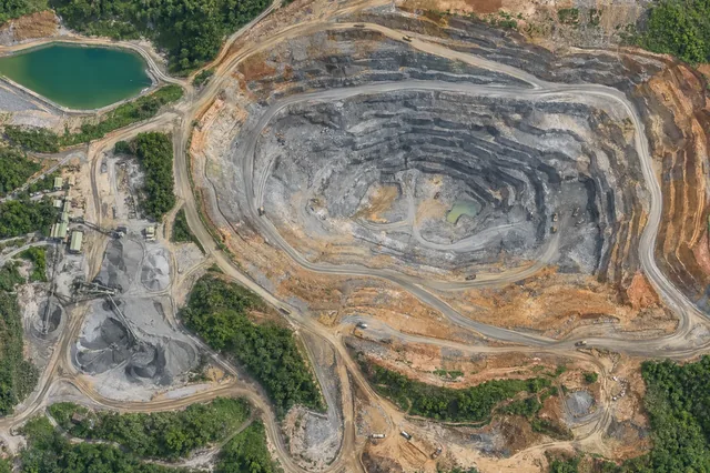
Surface differencing compares elevation observations across dates or versions. A numeric difference can result from real change, reference mismatch, grid alignment, occlusion or reconstruction uncertainty. The common valid area defines where a comparison is supported. Stable reference regions help distinguish systematic offsets from local physical changes.
Site conditions that can mislead interpretation
Tall buildings displace roofs, narrow streets are shadowed and courtyards may be hidden. Vehicles and temporary objects change between views. Legal boundaries cannot be inferred simply from visible fences or roofs. A geometrically valid dataset can still mix incompatible object definitions and produce misleading area totals.
A colored difference map does not prove that every nonzero cell changed physically. Unsupported or incompatible observations should remain excluded from the interpretation.
Prepare the inputs and the controlled test
Confirm horizontal and vertical references, observation dates and surface meanings. Align grids deliberately and preserve validity masks. Select stable comparison regions and independent evidence before interpreting the target changes. Keep any alignment correction separate from the resulting difference so the procedure remains auditable.
Build the comparison around a preserved baseline. Use the same input inventory, geographic extent and independent reference observations whenever the experiment permits. Change one justified factor at a time and record any unavoidable difference. Select both a difficult inspection region and a stable control region before examining the candidate output. Compare on their common valid support, then report any gain or loss of total coverage separately. This distinguishes a local improvement from a result that merely excludes the hardest observations.
Independent verification in this setting
Review a stratified sample including tall structures, low buildings, shadows and difficult boundaries. Check topology and compare uncertain interpretations with suitable independent evidence. Keep coordinate accuracy checks distinct from semantic validation. Resolve whether a disputed edge represents a roof, wall base or another feature before changing the geometry.
Inspect signed differences, spatial patterns and representative profiles. Review source photographs where an apparent change is consequential. Report excluded coverage and assess whether the observed signal is distinguishable from relevant uncertainty. Compare the same physical surface rather than canopy at one date and ground at another.
A linked check: Orthomosaic Seam Inspection
An orthomosaic combines image observations using reconstructed geometry and image selection. A visible seam can reflect exposure differences, moving objects, geometric inconsistency or source-image quality. Conversely, seamless color blending can hide a positional problem. Inspecting seams therefore requires both the stitched result and the original views that support the target features.
Select seams across representative surfaces and compare identifiable features on each side. Review original photographs, local surface support and capture timing. Separate radiometric discontinuity from geometric displacement. Preserve fixed viewing scales and reference locations when testing a blending or reconstruction change.
Check whether the candidate preserves feature position, edge continuity and valid coverage. Inspect stable control regions in addition to the most obvious seam. Compare independent evidence where geometry matters. Record whether the improvement concerns appearance, measurement support or both.
An illustrative decision example
Imagine a hypothetical quantity comparison in which two accepted top surfaces are almost identical, but the calculation uses different base assumptions near an uncertain boundary. The resulting volumes can differ materially even though both surfaces look smooth. Preserve the boundary and base definitions, inspect representative profiles and identify which assumptions change the result. Where ground support is missing, report the inferred component separately rather than calling it measured terrain. A candidate surface that fills every hole may increase apparent completeness while adding no independent observation. Compare common supported areas and describe the effect of any deliberate interpolation. This example illustrates sensitivity to evidence and reference definitions; it is not an inventory result. The receiving team should be able to reproduce the quantity and distinguish changes in the physical surface from changes in calculation assumptions, vertical reference or the chosen valid-area mask.
Interpret uncertainty before accepting the result
Write the acceptance rule before selecting the most attractive output. The actual threshold must follow the project purpose and the quality of the independent evidence. Inspect signed differences and spatial patterns as well as summaries. Investigate consequential outliers using their source observations instead of deleting them to improve a score. A result can be suitable for inspection planning while remaining unsuitable for a more demanding engineering or quantitative claim. State that intended-use boundary explicitly.
Deliver evidence that the next team can use
Deliver feature definitions, stable identifiers, confidence notes and topology rules. Preserve uncertain or unobservable objects instead of forcing a complete inventory. Receiving GIS users should know exactly what each polygon represents and which interpretation evidence supports it.
Keep the accepted source dates, processing version, coordinate conventions, masks and reference evidence beside the delivered data. Reopen a representative output from a clean copy and confirm that the intended receiving application interprets it consistently. Identify any remaining unsupported areas and the additional observation that would resolve them. The next analyst should be able to reconstruct the decision without depending on a temporary browser session, an operator recollection or a file whose name merely says final.
Where a cloud workflow can help
Online Photogrammetry Software can simplify the transfer from an organized image collection to a shared review workflow, but it does not remove acquisition or validation responsibilities. Drone Collab can be considered as part of that workflow after the team checks the current published capabilities and the outputs required by the project. Start with a representative collection and evaluate the evidence, usability and handover together. Choose the workflow because it supports a defensible decision rather than because one preview looks particularly polished.