The site decision and observation unit
This guide examines side image overlap when a mapping team needs to maintain a traceable estate inspection and crown-inventory register. The goal is to connect a specific technical choice to observable site evidence, an independently checkable comparison and a clear delivery decision.
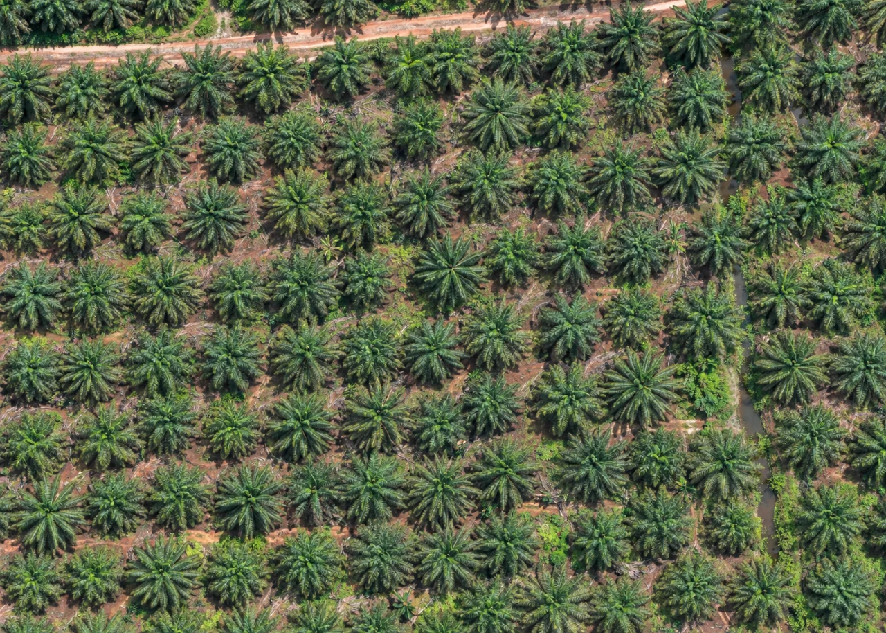
A visible crown, a planting station and a productive palm are different inventory objects. Organize observations by estate block, planting year and row direction. Drains, conservation strips and access corridors explain legitimate gaps in a planting pattern. Assign persistent identifiers so later observations can distinguish a replacement palm from a changed interpretation of an existing crown.
Define the decision before choosing a processing configuration. State the target object, the observable surface, the required geographic reference and the evidence needed by the receiving user. Separate direct observations from inferred values. This prevents an attractive image from becoming an unsupported claim about conditions that the sensor did not observe. Preserve the project question in the run record so later quality review evaluates the intended use rather than a convenient software statistic.
The technical mechanism
Side overlap connects neighboring flight lines. The shared surface must remain visible across both viewing geometries. Relief, tall structures and changes in camera height can narrow the useful common strip. Strong along-track matching does not guarantee that the whole block is well connected across tracks, especially where repetitive texture or occlusion removes distinctive features.
Site conditions that can mislead interpretation
Mature crowns overlap, young replacements disappear into ground vegetation, and pruning changes apparent crown size. Shadow and foliage movement can alter local texture between passes. A pale crown is an observation requiring investigation rather than an aerial disease diagnosis. Canopy geometry should not be presented as measured terrain beneath closed palm cover.
Uniform spacing over a map does not guarantee uniform overlap above a changing canopy or steep ground. The actual visible surface determines the footprint.
Prepare the inputs and the controlled test
Inspect the footprint relationship of neighboring lines over the highest and most obstructed surfaces. Review cross-track tie support in a representative block. If an adjustment is needed, preserve the original plan and change the relevant spacing deliberately. Confirm that boundary lines still observe the intended outside margin rather than merely intersect the delivery polygon.
Build the comparison around a preserved baseline. Use the same input inventory, geographic extent and independent reference observations whenever the experiment permits. Change one justified factor at a time and record any unavoidable difference. Select both a difficult inspection region and a stable control region before examining the candidate output. Compare on their common valid support, then report any gain or loss of total coverage separately. This distinguishes a local improvement from a result that merely excludes the hardest observations.
Independent verification in this setting
Inspect matched planting stations and exceptions, including apparently normal comparison palms. Record young replacements, multiple stems, recent pruning and intentional vacant areas. Match each field photograph to a block and crown identifier. Check access and drainage observations with estate personnel, since a visible track may not be trafficable and a dark channel does not reveal its invert level.
Look for seams, discontinuities and separate alignment components between lines. Compare independent checks across the width of the block. Evaluate both interior connection and edge support. A revised plan should be judged on demonstrated shared observations and resulting geometry, with additional capture volume recorded as an operational cost.
A linked check: Independent Checkpoint Design
Independent checkpoints evaluate geometry without participating in the adjustment being tested. Their reference quality, distribution and feature identification affect the result. Points used as control cannot simultaneously provide an independent accuracy assessment of that same adjustment. A useful design covers the conditions relevant to the delivered product rather than clustering checks on the easiest accessible surface.
Define the intended horizontal and vertical checks before processing. Separate control and checkpoint identifiers and preserve their observation methods. Choose visible stable targets distributed across meaningful terrain and acquisition conditions. Document reference uncertainty and any target-identification limitations. Keep withheld points withheld during the comparison.
Inspect signed residuals, spatial patterns and outliers with their evidence. Investigate mistaken identification or changed targets rather than removing inconvenient points automatically. Compare candidates on the same independent set and report exclusions with reasons. Present the reference method so the residuals are not interpreted more precisely than the check observations allow.
An illustrative decision example
Consider an illustrative pilot mission with a nominal image footprint one hundred metres wide. If the distance to the visible surface falls by one fifth while the camera remains unchanged, the footprint also becomes approximately one fifth narrower under the same projection assumptions. A line spacing that worked above lower ground can therefore leave less shared surface over a taller canopy or structure. The practical response is to inspect the limiting part of the site and revise the actual capture geometry, not simply to copy the overlap percentage from an earlier mission. Keep the example separate from an operational flight instruction: the real plan also depends on the aircraft, target visibility and applicable site constraints. After a revised pilot, compare sharp target detail and connection across neighboring views. Accept the plan only when the recorded observations support the intended product. The calculation explains sensitivity to camera distance; it does not predict positional accuracy or guarantee that an obscured target becomes visible.
Interpret uncertainty before accepting the result
Write the acceptance rule before selecting the most attractive output. The actual threshold must follow the project purpose and the quality of the independent evidence. Inspect signed differences and spatial patterns as well as summaries. Investigate consequential outliers using their source observations instead of deleting them to improve a score. A result can be suitable for inspection planning while remaining unsuitable for a more demanding engineering or quantitative claim. State that intended-use boundary explicitly.
Deliver evidence that the next team can use
Provide a dated crown or access register with confirmed, uncertain and unobservable records. Separate the imagery observation from productive status and field diagnosis. Operations teams can then resolve exceptions without treating every aerial detection as an equivalent producing palm.
Keep the accepted source dates, processing version, coordinate conventions, masks and reference evidence beside the delivered data. Reopen a representative output from a clean copy and confirm that the intended receiving application interprets it consistently. Identify any remaining unsupported areas and the additional observation that would resolve them. The next analyst should be able to reconstruct the decision without depending on a temporary browser session, an operator recollection or a file whose name merely says final.
Where a cloud workflow can help
Online Photogrammetry Software can simplify the transfer from an organized image collection to a shared review workflow, but it does not remove acquisition or validation responsibilities. Drone Collab can be considered as part of that workflow after the team checks the current published capabilities and the outputs required by the project. Start with a representative collection and evaluate the evidence, usability and handover together. Choose the workflow because it supports a defensible decision rather than because one preview looks particularly polished.