The site decision and observation unit
This guide examines lens distortion review when a mapping team needs to organize solar-site geometry and visible-condition observations. The goal is to connect a specific technical choice to observable site evidence, an independently checkable comparison and a clear delivery decision.
Use panel rows, service lanes, drainage features and site blocks as separate objects. An RGB mosaic supports layout and visible-surface interpretation. Thermal inspection is a different measurement task with its own acquisition and calibration requirements. Keep the sensor type, capture conditions and intended observation explicit in the project register.
Define the decision before choosing a processing configuration. State the target object, the observable surface, the required geographic reference and the evidence needed by the receiving user. Separate direct observations from inferred values. This prevents an attractive image from becoming an unsupported claim about conditions that the sensor did not observe. Preserve the project question in the run record so later quality review evaluates the intended use rather than a convenient software statistic.
The technical mechanism
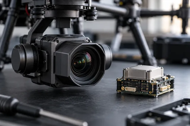
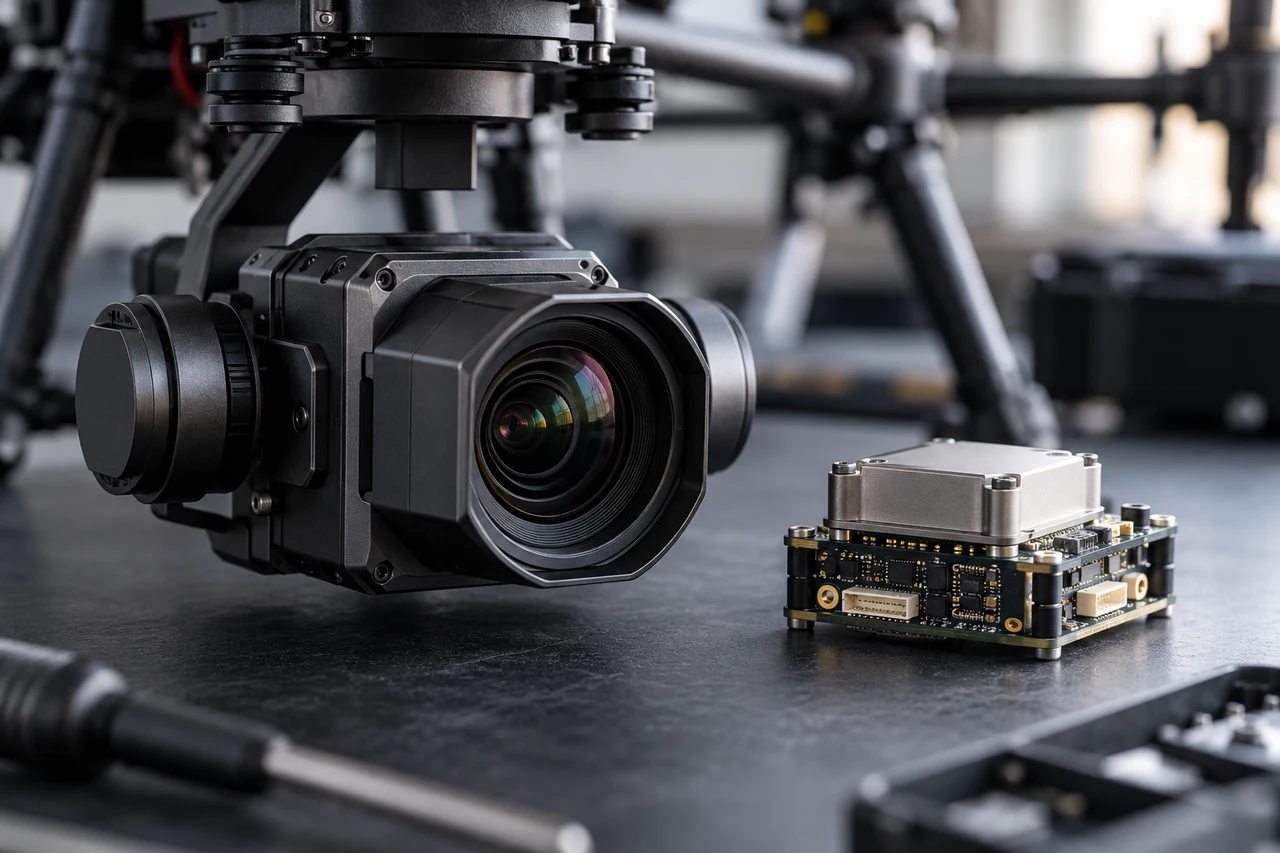
Lens distortion changes the relationship between ideal projection and recorded image coordinates. The chosen camera model must represent the actual optical behavior sufficiently for the task. Incorrect distortion assumptions can create spatially organized residuals or surface deformation. Image cropping and resizing also affect the coordinate frame in which the camera parameters are meaningful.
Site conditions that can mislead interpretation
Repeated panel patterns can confuse matching, specular reflections change between views and rows occlude ground beneath them. Shadows may resemble damaged or missing panels. An RGB image cannot establish an electrical fault or a calibrated temperature anomaly. Smooth reconstructed geometry does not verify concealed wiring or foundations.
A more flexible distortion model can absorb other weaknesses. Extra parameters are useful only when the available image geometry and evidence can constrain them.
Prepare the inputs and the controlled test
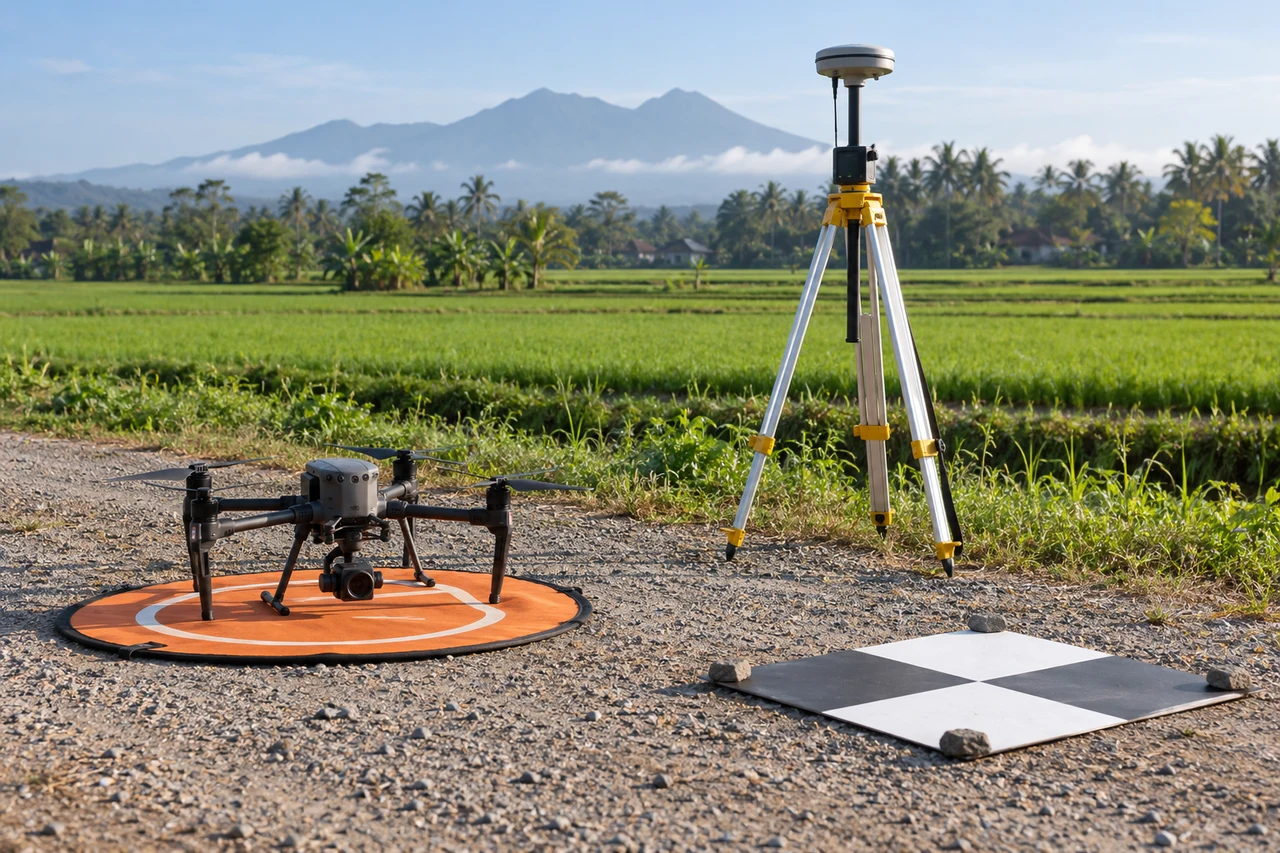
Preserve original dimensions and document any preprocessing. Confirm that camera metadata and the chosen projection model are compatible. Compare a controlled candidate using suitable reference features distributed across the block. Inspect images with targets near both central and peripheral image regions rather than relying only on the visually clean center.
Build the comparison around a preserved baseline. Use the same input inventory, geographic extent and independent reference observations whenever the experiment permits. Change one justified factor at a time and record any unavoidable difference. Select both a difficult inspection region and a stable control region before examining the candidate output. Compare on their common valid support, then report any gain or loss of total coverage separately. This distinguishes a local improvement from a result that merely excludes the hardest observations.
Independent verification in this setting
Check row identifiers, selected visible anomalies and access connections using appropriate site evidence. Verify geometric references on suitable stable surfaces. Where thermal or electrical interpretation is intended, use the corresponding qualified inspection method rather than inferring it from RGB appearance. Record uncertain reflections separately from confirmed visible damage.
Review independent geometry, residual direction and surface shape at common locations. Check whether a model change improves external observations instead of merely reducing an internal fit measure. Retain parameter files and input-image identity so the accepted result can be reproduced.
A linked check: Independent Checkpoint Design
Independent checkpoints evaluate geometry without participating in the adjustment being tested. Their reference quality, distribution and feature identification affect the result. Points used as control cannot simultaneously provide an independent accuracy assessment of that same adjustment. A useful design covers the conditions relevant to the delivered product rather than clustering checks on the easiest accessible surface.
Define the intended horizontal and vertical checks before processing. Separate control and checkpoint identifiers and preserve their observation methods. Choose visible stable targets distributed across meaningful terrain and acquisition conditions. Document reference uncertainty and any target-identification limitations. Keep withheld points withheld during the comparison.
Inspect signed residuals, spatial patterns and outliers with their evidence. Investigate mistaken identification or changed targets rather than removing inconvenient points automatically. Compare candidates on the same independent set and report exclusions with reasons. Present the reference method so the residuals are not interpreted more precisely than the check observations allow.
An illustrative decision example
Imagine a controlled comparison in which a baseline reconstructs most of a site, while a candidate produces a cleaner-looking surface after excluding difficult images. If the excluded observations cover a critical boundary, the smoother result may be less useful despite its attractive appearance. Compare the common valid area first, then inspect the coverage lost by the candidate. Use the same independent reference locations and review original images around the difficult target. If the candidate improves stable geometry but leaves the target unsupported, record both outcomes rather than calling the entire run better. A targeted supplementary capture may be more appropriate than stronger smoothing. This hypothetical example illustrates why internal fit, visual quality and supported delivery area must remain separate observations. It supplies no measured performance claim. The accepted configuration should address the actual mechanism under investigation and retain the evidence needed for the next reviewer to understand the choice.
Interpret uncertainty before accepting the result
Write the acceptance rule before selecting the most attractive output. The actual threshold must follow the project purpose and the quality of the independent evidence. Inspect signed differences and spatial patterns as well as summaries. Investigate consequential outliers using their source observations instead of deleting them to improve a score. A result can be suitable for inspection planning while remaining unsuitable for a more demanding engineering or quantitative claim. State that intended-use boundary explicitly.
Deliver evidence that the next team can use
Provide row-linked observations, sensor context and valid coverage. Keep maintenance decisions connected to verified inspection findings. The map should distinguish visible layout evidence from electrical performance and any thermal product that may be delivered separately.
Keep the accepted source dates, processing version, coordinate conventions, masks and reference evidence beside the delivered data. Reopen a representative output from a clean copy and confirm that the intended receiving application interprets it consistently. Identify any remaining unsupported areas and the additional observation that would resolve them. The next analyst should be able to reconstruct the decision without depending on a temporary browser session, an operator recollection or a file whose name merely says final.
Where a cloud workflow can help
Drone Mapping Software can simplify the transfer from an organized image collection to a shared review workflow, but it does not remove acquisition or validation responsibilities. Drone Collab can be considered as part of that workflow after the team checks the current published capabilities and the outputs required by the project. Start with a representative collection and evaluate the evidence, usability and handover together. Choose the workflow because it supports a defensible decision rather than because one preview looks particularly polished.